1,385
社区成员
 发帖
发帖 与我相关
与我相关 我的任务
我的任务
 分享
分享
NVIDIA BlueField DPU (数据处理器)可用于网络功能加速。这种网络卸载可以用DPDK,也可以用NVIDIA DOCA软件框架。
在本系列中,我构建了一个应用并用两种方式进行了卸载:DPDK和NVIDIA DOCA SDK。我将每个步骤记录为一个单独的代码补丁,并在每个系列中提供完整的步骤。这部分将向您展示如何用DPDK编程 BlueField DPU 。
首先,我需要一个简单但有意义的用例来在 DPU 上部署应用程序。我选择了基于策略的路由( PBR )来根据第 3 层和第 4 层数据包属性将流量引导到不同的网关,覆盖(或补充) X86 主机选择的网关。现实世界中有各种原因需要这样做,包括以下示例:
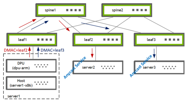
图 1 . 使用 PBR 将流量从主机引导到两个网关之一
我在 DPU (BF2-ARM)上使用 PBR 将流量从主机(server1-x86)引导到两个网关[leaf2, leaf3]之一。叶交换机随后将流量转发给其本地连接的选播服务提供商[server2, server3]。
第一个问题:我是写一个全新的应用程序,还是卸载一个现有的应用程序?
我决定卸载我最喜欢的开源路由软件栈 FRRouting ( FRR )的 PBR 功能。这使我能够扩展现有的代码库,并与现有的 sample apps 形成很好的对比。 FRR有一个支持多种数据平面插件的框架,可以轻松用DPDK和DOCA实现新的数据平面插件并集成到FRR。
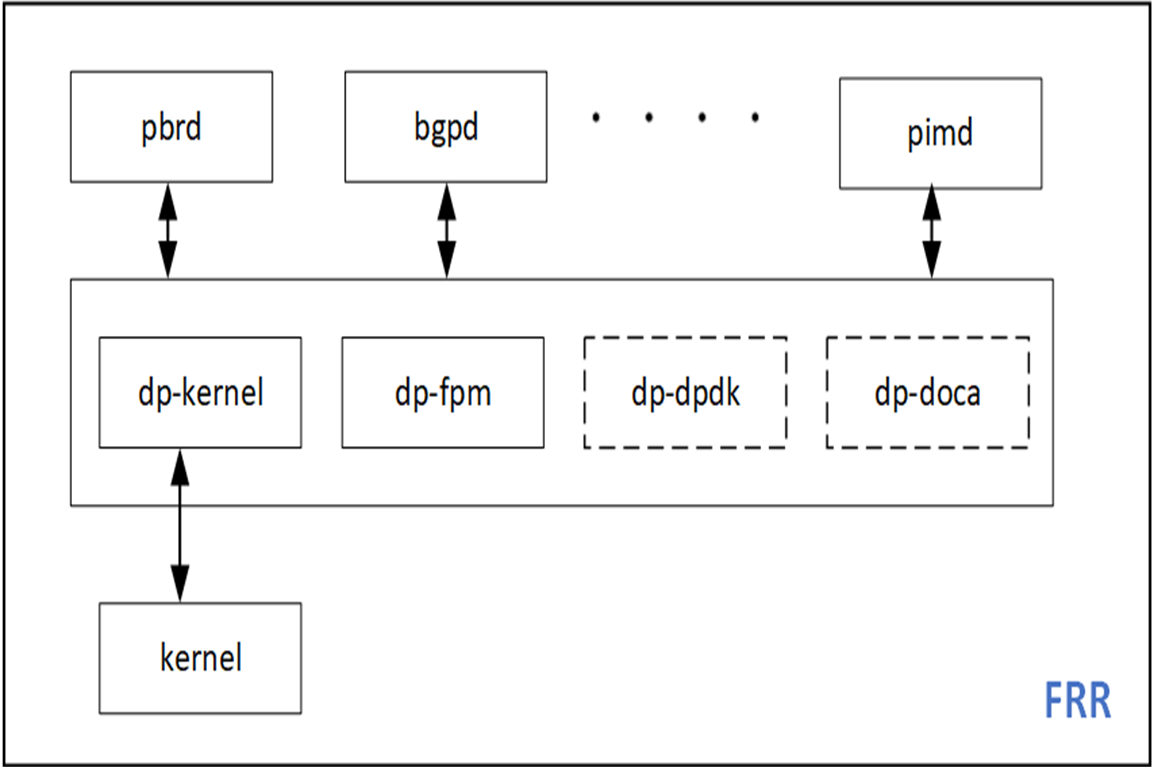
图 2 . DPDK 和 DOCA 插件可以很容易地添加到 FRR中
在本节中,我将介绍创建具有 DPU 硬件加速功能的应用程序所需的准备工作。
我有一个x86服务器并在上面安装了一块BlueFied-2 DPU, 该 DPU 有两个 25G 上行链路和一个带有 8GB内存的ARM处理器 。有关硬件安装的更多信息,请参阅 DOCA SDK 文档 。您也可以使用 DPU PocKit 来构建和引导你的系统环境.
我安装了 BlueField 启动流文件( BFB ),它为 DPU 提供了 Ubuntu 操作系统映像,并附带了 DOCA-1.2 和 DPDK-20.11.3 的库。
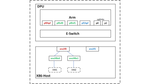
图 3 . Netdev Representors
使用 SR-IOV ,我在主机上为两个虚拟机创建了两个虚拟函数( VF )接口。
root@server1-x86:~# echo 2 > /sys/class/net/ens3f0/device/sriov_numvfs
主机上的PF和VF分别映射到 DPU ARM上的以下 netdev representors 。
|
Netdev Type |
Host netdev |
DPU netdev |
|
PF |
ens3f0 [vf0, vf1] |
pf0hpf |
|
VF |
ens3f0v0 |
pf0vf0 |
|
VF |
ens3f0v1 |
pf0vf1 |
表 1 .主机上PF和VF的映射
首先,我使用 DPDK 的 testpmd 进行了我的用例的原型化设计,它位于 DPU 的/ opt / mellanox /目录下
包括testpmd在内的任何DPDK应用程序都必须设置hugepages。
root@dpu-arm:~# echo 1024 > /sys/kernel/mm/hugepages/hugepages-2048kB/nr_hugepages
(可选)保留配置,使其在 DPU 重新启动后仍然有效。
root@dpu-arm:~# echo "vm.nr_hugepages = 1024" > /etc/sysctl.d/99-hugepages.conf
启动testpmd。
root@dpu-arm:~# /opt/mellanox/dpdk/bin/dpdk-testpmd -- --total-num-mbufs=100000 --flow-isolate-all -i
Testpmd会消耗比较多的内存,默认情况下会分配3.5GB 。由于我不需要在 CPU 中处理数据流量,我把total-mem的值设定为200M ,其中total-mem = total-num-mbufs * mbuf-size(默认mbuf-size为 2048 字节)。我还使用了flow-isolation模式,因为我必须将 ARP 数据包发送到 DPU 上的内核网络堆栈来解析PBR的下一跳)。初始化完成后,-i选项使得testpmd进入交互式shell 。
作为testpmd完成rte_eal初始化的一部分,mlx5_pci设备被探测并成为可以被访问的DPDK端口。
testpmd> show port summary all

Number of available ports: 6

Port MAC Address Name Driver Status Link

0 04:3F:72:BF:AE:38 0000:03:00.0 mlx5_pci up 25 Gbps

1 4A:6B:00:53:79:E5 0000:03:00.0_representor_vf4294967295 mlx5_pci up 25 Gbps

2 62:A1:93:8D:68:C4 0000:03:00.0_representor_vf0 mlx5_pci up 25 Gbps

3 0A:8E:97:F5:C0:41 0000:03:00.0_representor_vf1 mlx5_pci up 25 Gbps

4 04:3F:72:BF:AE:39 0000:03:00.1 mlx5_pci up 25 Gbps

5 D2:0B:15:45:94:E8 0000:03:00.1_representor_vf4294967295 mlx5_pci up 25 Gbps

testpmd>
您在这里看到的 DPDK 端口对应 PF / VF representor和两个上行链路。
|
DPDK port |
DPU netdev |
Comments |
|
0 |
p0 |
25G uplink attached to leaf1 |
|
1 |
pf0hpf | |
|
2 |
pf0vf0 |
VM1 |
|
3 |
pf0vf1 |
VM2 |
|
4 |
p1 | |
|
5 |
pf1hpf |
表 2 . DPDK 端口映射
接下来,通过定义ingress port、源 IP 、目标 IP 、协议和端口,我用rte_flow下发了PBR规则。除此之外,我还定义了对匹配数据包采取的ACTION。源 MAC 和目标 MAC 被重写, TTL 被递减,出口端口被设置为物理上行链路p0。
In-port=pf0vf0, match [SIP=172.20.0.8, DIP=172.30.0.8, IP-proto=UDP, UDP-dport=53], actions [dec-ttl, set-src-mac=p0-mac, set-dst-mac=leaf2-MAC, out-port=p0]
这条PBR 规则从VM1接收DNS 流量,并将其发送到特定的 GW (leaf2, server2)。我还增加了一个计数器以便故障定位。
testpmd> flow create 2 ingress transfer pattern eth / ipv4 src is 172.20.0.8 dst is 172.30.0.8 proto is 17 / udp dst is 53 / end actions dec_ttl / set_mac_src mac_addr 00:00:00:00:00:11 / set_mac_dst mac_addr 00:00:5e:00:01:fa / port_id id 0 / count / end

Flow rule #0 created

testpmd>
DPU 卸载可以工作在Switch(FDB)模式,也可以工作在NIC模式。在这个用例中,经过几次数据包修改后,我需要将流量从 X86 主机重定向到 25G 上行链路。所以从概念上讲,这里使用了Switch ( FDB) 模式,因此需要设置rte_flow的transfer属性。
我从VM1发送了一些流量,看看它是否与我用testpmd创建的flow是否匹配,可以通过执行query <port-id, flow-id>命令来查看。
testpmd> flow query 2 0 count

COUNT:

hits_set: 1

bytes_set: 1

hits: 22

bytes: 2684

testpmd>
结果是匹配的,在leaf2/server2上可以看到这些流量且具有修改后的数据包头。因为被操作的流量是 DNS ,所以为了测试流量,我从VM1发送 DNS 请求。为了控制流量速率和其他数据包字段,我使用 mz 来生成测试流量。
ip netns exec vm1 mz ens3f0v0 -a 00:de:ad:be:ef:01 -b 00:de:ad:be:ef:02 -A 172.20.0.8 -B 172.30.0.8 -t udp "sp=25018, dp=53" -p 80 -c 0 -d 1s
另一个健全性检查是查看此流是否真的被卸载。有两种方法可以做到这一点:
mlx_steering_dump允许您查看硬件上已经下发成功的流规则。使用git下载并安装该工具。
root@dpu-arm:~# git clone https://github.com/Mellanox/mlx_steering_dump
使用mlx_steering_dump_parser.py脚本验证硬件中下发的流规则。
root@dpu-arm:~# ./mlx_steering_dump/mlx_steering_dump_parser.py -p `pidof dpdk-testpmd`  -f /tmp/dpdkDump

domain 0xbeb3302, table 0xaaab23e69c00, matcher 0xaaab23f013d0, rule 0xaaab23f02650

   match: outer_l3_type: 0x1, outer_ip_dst_addr: 172.30.0.8, outer_l4_type: 0x2, metadata_reg_c_0: 0x00030000, outer_l4_dport: 0x0035, outer_ip_src_addr: 172.20.0.8

   action: MODIFY_HDR, rewrite index 0x0 & VPORT, num 0xffff & CTR(hits(154), bytes(18788)),
此命令打印出 testpmd 应用程序下发的所有流规则。我们可以看到硬件上设置的外部 头匹配信息和前面RTE_FLOW定义的匹配[SIP = 172.20.0.8 , DIP = 172.30.0.8 , IP proto = UDP , UDP dport = 53]是一致的。作为打印输出的一部分,流量计数器的值也被读取并被重置。
原型设计,作为应用程序设计思维过程的最后一步现在已经完成。我现在知道我可以在 DPDK 中建立一个 PBR 规则,把它安装在硬件中并对我们感兴趣的数据报文进行修改。现在在下一节中添加 DPDK 数据平面。
在本节中,我将通过向 Zebra 添加一个 DPDK 数据平面插件,介绍 DPU 对 PBR进行 硬件加速的步骤。我将这些步骤分解为单独的代码提交,整个补丁集以 reference 的形式提供。
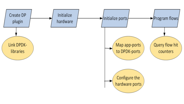
图 4 .基于策略的路由 DPDK 卸载工作流
由于目标体系结构是 DPU Arm ,因此可以直接在 DPU Arm上构建、在 X86 CPU 上交叉编译或在云中构建。在这篇文章中,我直接在 DPU Arm 上进行编码和构建。
以 root 用户身份运行应用程序
FRR 通常作为非 root 用户运行。 FRR 可以下载和上传整个互联网路由表;这可能会出什么问题?然而,几乎所有的 DPDK 应用程序都是以 root 用户身份运行, DPDK 库和驱动程序也都是基于这样设计的。
经过多次实验,并使用 root 用户选项重新编译FRR, 我还是无法让 FRR 作为非 root 用户工作。这是可以接受的,因为我在一个安全的空间,即 DPU Arm 中运行 FRR 。
Zebra 是 FRR 中的一个守护进程,负责整合路由协议守护进程的更新并构建转发表。 Zebra 还有一个基础设施,可以将这些转发表推送到像 Linux 内核这样的数据平面。
FRR 有自己的构建系统,限制直接导入外部 make 文件。由于 pkg-config 的简单优雅,将相关库链接到 Zebra 很容易。
我找到了libdpdk.pc并将其添加到PKG_CONFIG_PATH值中:
root@dpu-arm:~# find /opt/mellanox/ -name libdpdk.pc

/opt/mellanox/dpdk/lib/aarch64-linux-gnu/pkgconfig/libdpdk.pc

root@dpu-arm:~# export PKG_CONFIG_PATH=$PKG_CONFIG_PATH:/opt/mellanox/dpdk/lib/aarch64-linux-gnu/pkgconfig
Pkg-config为您提供了以下抽象:
root@dpu-arm:~# pkg-config --libs libdpdk
-L/opt/mellanox/dpdk/lib/aarch64-linux-gnu -Wl,--as-needed -lrte_node -lrte_graph -lrte_bpf -lrte_flow_classify -lrte_pipeline -lrte_table -lrte_port -lrte_fib -lrte_ipsec -lrte_vhost -lrte_stack -lrte_security -lrte_sched -lrte_reorder -lrte_rib -lrte_regexdev -lrte_rawdev -lrte_pdump -lrte_power -lrte_member -lrte_lpm -lrte_latencystats -lrte_kni -lrte_jobstats -lrte_gso -lrte_gro -lrte_eventdev -lrte_efd -lrte_distributor -lrte_cryptodev -lrte_compressdev -lrte_cfgfile -lrte_bitratestats -lrte_bbdev -lrte_acl -lrte_timer -lrte_metrics -lrte_cmdline -lrte_pci -lrte_ethdev -lrte_meter -lrte_ip_frag -lrte_net -lrte_mbuf -lrte_mempool -lrte_hash -lrte_rcu -lrte_ring -lrte_eal -lrte_telemetry -lrte_kvargs -lbsd
root@dpu-arm:~#
root@dpu-arm:~# pkg-config --cflags libdpdk
-include rte_config.h -mcpu=cortex-a72 -I/opt/mellanox/dpdk/include/dpdk -I/opt/mellanox/dpdk/include/dpdk/../aarch64-linux-gnu/dpdk -I/opt/mellanox/dpdk/include/dpdk -I/usr/include/libnl3
root@dpu-arm:~#
我在 FRR makefile (configure.ac)中为 DPDK 添加了pkg check-and-define宏。
if test "$enable_dp_dpdk" = "yes"; then

 PKG_CHECK_MODULES([DPDK], [libdpdk], [

 AC_DEFINE([HAVE_DPDK], [1], [Enable DPDK backend])

 DPDK=true

 ], [

 AC_MSG_ERROR([configuration specifies --enable-dp-dpdk but DPDK libs were not found])

 ])

fi
我将 DPDK libs和cflags抽象包含在zebra-dp-dpdk make宏(zebra/subdir.am)中。
zebra_zebra_dplane_dpdk_la_LIBADD = $(DPDK_LIBS)

zebra_zebra_dplane_dpdk_la_CFLAGS = $(DPDK_CFLAGS)
有了这些,我就有了构建插件所需的所有头文件和库。
第一步是初始化硬件。
char*argv[] = {"/usr/lib/frr/zebra", "--"};

rc = rte_eal_init(sizeof(argv) / sizeof(argv[0]), argv);
这将探测 PCIe 设备并填充 DPDK rte_eth_dev数据库。
接下来设置硬件端口。
FRR 有自己的基于 Linux netdevs表的接口(端口)表,该表使用 NetLink 更新填充,并使用ifIndex键值来索引。 PBR 规则锚定到此表中的一个接口。要编程 PBR 数据平面条目,需要一个 Linux ifIndex和 DPDK port-id值之间的映射表。netdev信息已经在 DPDK 驱动程序中可用,可以通过rte_eth_dev_info_get查询。
struct rte_eth_dev_info *dev_info

RTE_ETH_FOREACH_DEV(port_id) {

 /* dev_info->if_index is used for setting up the dpdk port_id<=>if_index mapping table

 * in zebra */

 rte_eth_dev_info_get(port_id, dev_info);

}
此外,所有端口都需要置于flow-isolation模式并启动。
rte_flow_isolate(port_id, 1, &error);
Flow-isolation模式将未命中数据包发送到内核网络堆栈,允许它处理 ARP 请求之类的事情。
rte_eth_dev_start(port_id);
PBR 规则现在需要用rte_flow来编写,下面是一个示例规则:
In-port=pf0vf0, match [SIP=172.20.0.8, DIP=172.30.0.8, IP-proto=UDP, UDP-dport=53], actions [set-src-mac=p0-mac, set-dst-mac=leaf2-MAC, dec-ttl, out-port=p0]
这些参数通过rte_flow_attributes、rte_flow_item (match)和rte_flow_action数据结构填充。
此数据结构用于指示 PBR 流用于分组重定向或 transfer flow 。
static struct rte_flow_attr attrs = {.ingress = 1, .transfer = 1};
DPDK 为数据包头中的每一层使用{key, mask}匹配结构:以太网、 IP 、 UDP 等。
struct rte_flow_item_eth eth, eth_mask;

struct rte_flow_item_ipv4 ip, ip_mask;

struct rte_flow_item_udp udp, udp_mask;
填充这些数据结构需要大量重复的代码。
DPDK 为每个Action使用单独的数据结构,然后允许您在创建流规则时以可变长度数组的形式提供所有Actions。有关Actions如下:
struct rte_flow_action_set_mac conf_smac, conf_dmac;

struct rte_flow_action_port_id conf_port;

struct rte_flow_action_count conf_count;
填充这些数据结构同样只是机械的。
作为可选项,您可以验证rte_flow_attr、rte_flow_item和rte_flow_action列表。
rc = rte_flow_validate(port_id, &attrs, items, actions, &error);
流验证通常用于检查底层 DPDK 驱动程序是否支持特定的流配置。流验证是一个可选步骤,在最后的代码中,您可以直接跳转到流创建。
flow_ptr = rte_flow_create(port_id, &attrs, items, actions, &error);
Rte_flow命令被锚定到输入端口。可以创建多个流条目组并将这些组链起来。即使流条目不存在链的第一个组中,也就是不在 组0中,它仍然必须锚定到输入端口。group-0存在性能限制。
流量插入率在group-0中受到限制。要绕过该限制,您可以在group-0中安装一个默认流,以“跳转到group-1”,然后在group-1中创建流规则。
流创建 API 返回一个流指针,该指针必须被缓存以进行后续的流删除。
rc = rte_flow_destroy(port_id, flow_ptr, &error);
FRR-PBR 守护进程管理状态机来解析,添加或删除 PBR 流。因此,我不必使用 DPDK 的原生函数来老化PBR规则。
在创建流时,我将计数操作附加到流。可用于查询流量统计信息和命中次数。
struct rte_flow_query_count query;
rte_flow_query(port_id, flow_ptr, actions, &query, &error);
为了便于测试和验证,我将该统计显示插入了 FRR 的vtysh CLI 。
我以 root 用户的身份启动了 FRR ,并通过/etc/frr/daemons文件启用了新添加的 DPDK 插件:
zebra_options= " -M dplane_dpdk -A 127.0.0.1"
DPDK-port映射表的 FRR 接口已填充:
root@dpu-arm:~# systemctl restart frr

root@dpu-arm:~# vtysh -c "show dplane dpdk port"

Port Device    IfName    IfIndex    sw,domain,port

0 0000:03:00.0 p0        4          0000:03:00.0,0,65535

1 0000:03:00.0 pf0hpf    6          0000:03:00.0,0,4095

2 0000:03:00.0 pf0vf0    15         0000:03:00.0,0,4096

3 0000:03:00.0 pf0vf1    16         0000:03:00.0,0,4097

4 0000:03:00.1 p1        5          0000:03:00.1,1,65535

5 0000:03:00.1 pf1hpf    7          0000:03:00.1,1,20479

root@dpu-arm:~#
接下来,我将 PBR 规则配置为匹配来自 VM1 的 DNS 流量,并使用frr.conf将其重定向到 leaf2 。
!

interface pf0vf0

pbr-policy test

!

pbr-map test seq 1

match src-ip 172.20.0.8/32

match dst-ip 172.30.0.8/32

match dst-port 53

match ip-protocol udp

set nexthop 192.168.20.250

!
我从 VM1 发送DNS查询到 anycast DNS 服务器。
root@dpu-arm:~# vtysh -c "show dplane dpdk pbr flows"

Rules if pf0vf0

 Seq 1 pri 300

 SRC IP Match 172.20.0.8/32

 DST IP Match 172.30.0.8/32

 DST Port Match 53

 Tableid: 10000

 Action: nh: 192.168.20.250 intf: p0

 Action: mac: 00:00:5e:00:01:fa

 DPDK: installed 0x40

 DPDK stats: packets 14 bytes 1708

root@dpu-arm:~#
匹配流,并使用修改后的数据包头将流量转发到目的地leaf2/server2。这可以通过连接到流的计数器和使用mlx_steering_dump做硬件转储来验证。
root@dpu-arm:~# ./mlx_steering_dump/mlx_steering_dump_parser.py -p `pidof zebra` -f /tmp/dpdkDump

domain 0x32744e02, table 0xaaab07849cf0, matcher 0xffff20011010, rule 0xffff20012420

 match: outer_l3_type: 0x1, outer_ip_dst_addr: 172.30.0.8, outer_l4_type: 0x2, metadata_reg_c_0: 0x00030000, outer_l4_dport: 0x0035, outer_ip_src_addr: 172.20.0.8

 action: MODIFY_HDR(hdr(dec_ip4_ttl,smac=04:3f:72:bf:ae:38,dmac=00:00:5e:00:01:fa)), rewrite index 0x0 & VPORT, num 0xffff & CTR(hits(33), bytes(4026)), index 0x806200
FRR 现在有一个功能齐全的 DPDK 数据平面插件,可以在 DPU 硬件上卸载 PBR 规则。
这篇文章回顾了使用 DPDK RTE_FLOW库在 BlueField 上硬件加速 PBR 规则的 FRR 数据平面插件的创建。在下一篇文章中,我将带您了解 FRR DOCA 数据平面插件 并向您展示如何使用新的 DOCA_FLOW库卸载 PBR 规则。