405
社区成员
 发帖
发帖 与我相关
与我相关 我的任务
我的任务
 分享
分享
GD32207I-EVAL是-兆易创新推出的一款GD32F20X系列的评估板,最高主频高达120M,该开发板具有丰富的板载资源,可以充分发挥 GD32207IK的芯片性能。
开发板外观如下图所示:
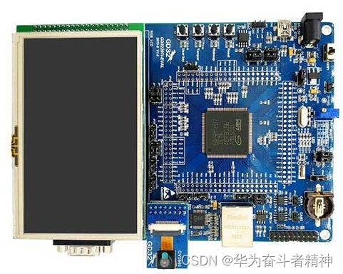
该开发板常用 板载资源 如下:
GD32207IK,主频 120MHz,3MB Flash、256KB SRAM
常用外设
调试接口:GD-LINK
本 BSP 目前对外设的支持情况如下:
| 片上外设 | 支持情况 | 备注 |
|---|---|---|
| GPIO | 支持 | PA0, PA1... ---> PIN: 0, 1...143 |
| UART | 支持 | UART0 - UART7 |
| I2C | 支持 | I2C1 |
| SPI | 支持 | SPI0 - SPI2 |
| SPI FLASH | 支持 | |
| ADC | 支持 | ADC0 - ADC2 |
| 扩展模块 | 支持情况 | 备注 |
| 暂无 | 暂不支持 | 暂不支持 |
使用说明分为如下两个章节:
快速上手
本章节是为刚接触 RT-Thread 的新手准备的使用说明,遵循简单的步骤即可将 RT-Thread 操作系统运行在该开发板上,看到实验效果 。
进阶使用
本章节是为需要在 RT-Thread 操作系统上使用更多开发板资源的开发者准备的。通过使用 ENV 工具对 BSP 进行配置,可以开启更多板载资源,实现更多高级功能。
本 BSP 为开发者提供 MDK4、MDK5 和 IAR 工程,并且支持 GCC 开发环境,也可使用RT-Thread Studio开发。下面以 MDK5 开发环境为例,介绍如何将系统运行起来。
使用数据线连接开发板到 PC,使用USB转232连接PA9(MCU TX)和PA10(MCU RX),打开电源开关。
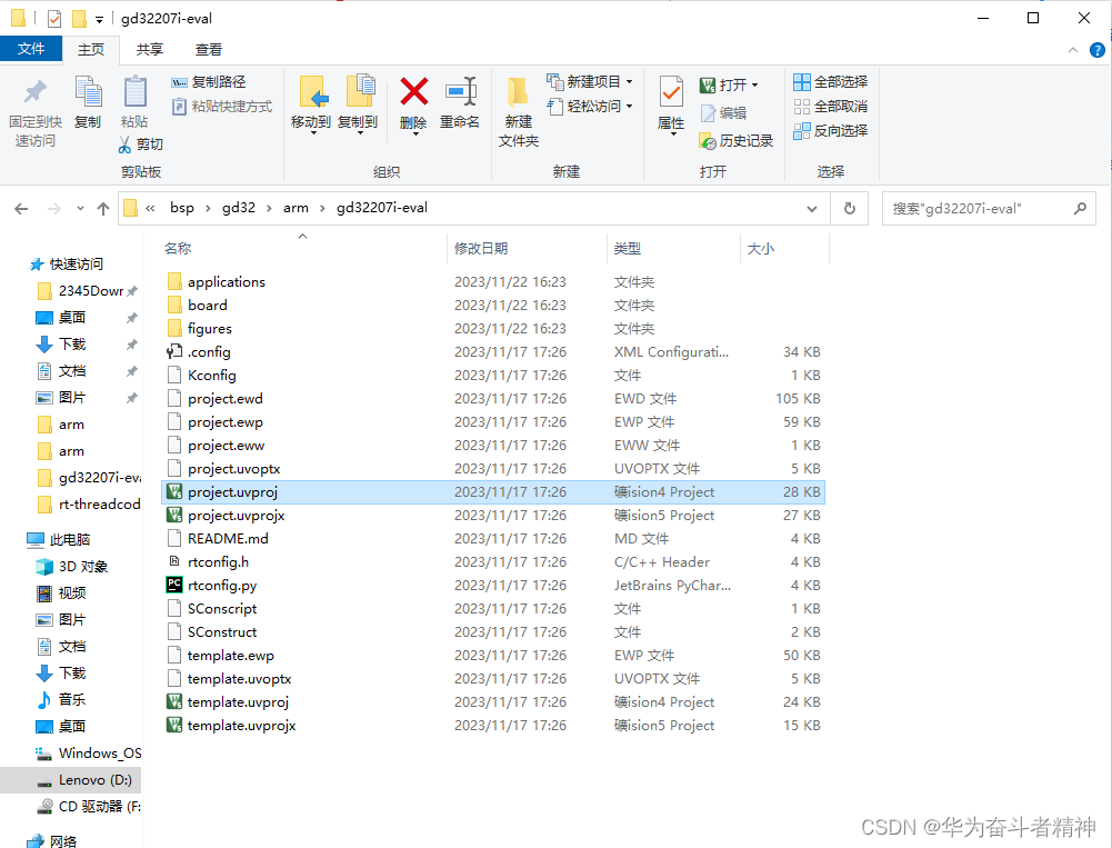
双击 project.uvprojx 文件,打开 MDK5 工程,编译并下载程序到开发板。
工程默认配置使用 GD-Link 仿真器下载程序,在通过 GD-Link 连接开发板的基础上,点击下载按钮即可下载程序到开发板
下载程序成功之后,系统会自动运行,LED 闪烁。
连接开发板对应串口到 PC , 在终端工具里打开相应的串口(115200-8-1-N),复位设备后,可以看到 RT-Thread 的输出信息:
 \ | /
- RT -     Thread Operating System
 / | \     4.1.0 build May  2 2022 23:45:28
 2006 - 2022 Copyright by RT-Thread team
msh >
此 BSP 默认只开启了 GPIO 和 串口0的功能,如果需使用高级功能,需要利用 ENV 工具对BSP 进行配置,步骤如下:
在 bsp 下打开 env 工具。
输入menuconfig命令配置工程,配置好之后保存退出。
输入pkgs --update命令更新软件包。
输入scons --target=mdk4/mdk5/iar 命令重新生成工程。
暂无
维护人:
..\bsp\gd32\arm\gd32207i-eval\board\board.c
/*
 * Copyright (c) 2006-2022, RT-Thread Development Team
 *
 * SPDX-License-Identifier: Apache-2.0
 *
 * Change Logs:
 * Date           Author       Notes
 * 2021-08-20     BruceOu      first implementation
 */
#include <stdint.h>
#include <rthw.h>
#include <rtthread.h>
#include <board.h>

/**
  * @brief  This function is executed in case of error occurrence.
  * @param  None
  * @retval None
  */
void Error_Handler(void)
{
    /* USER CODE BEGIN Error_Handler */
    /* User can add his own implementation to report the HAL error return state */
    while (1)
    {
    }
    /* USER CODE END Error_Handler */
}

/** System Clock Configuration
*/
void SystemClock_Config(void)
{
    SysTick_Config(SystemCoreClock / RT_TICK_PER_SECOND);
    NVIC_SetPriority(SysTick_IRQn, 0);
}

/**
 * This is the timer interrupt service routine.
 *
 */
void SysTick_Handler(void)
{
    /* enter interrupt */
    rt_interrupt_enter();

    rt_tick_increase();

    /* leave interrupt */
    rt_interrupt_leave();
}

/**
 * This function will initial GD32 board.
 */
void rt_hw_board_init()
{
    /* NVIC Configuration */
#define NVIC_VTOR_MASK              0x3FFFFF80
#ifdef  VECT_TAB_RAM
    /* Set the Vector Table base location at 0x10000000 */
    SCB->VTOR  = (0x10000000 & NVIC_VTOR_MASK);
#else  /* VECT_TAB_FLASH  */
    /* Set the Vector Table base location at 0x08000000 */
    SCB->VTOR  = (0x08000000 & NVIC_VTOR_MASK);
#endif

    SystemClock_Config();

#ifdef RT_USING_COMPONENTS_INIT
    rt_components_board_init();
#endif

#ifdef RT_USING_CONSOLE
    rt_console_set_device(RT_CONSOLE_DEVICE_NAME);
#endif

#ifdef BSP_USING_SDRAM
    rt_system_heap_init((void *)EXT_SDRAM_BEGIN, (void *)EXT_SDRAM_END);
#else
    rt_system_heap_init((void *)HEAP_BEGIN, (void *)HEAP_END);
#endif
}

/*@}*/
..\bsp\gd32\arm\libraries\gd32_drivers\drv_gpio.c
/**
  * @brief  get pin
  * @param  pin
  * @retval None
  */
const struct pin_index *get_pin(rt_uint8_t pin)
{
    const struct pin_index *index;

    if (pin < ITEM_NUM(pins))
    {
        index = &pins[pin];
        if (index->index == -1)
        index = RT_NULL;
    }
    else
    {
        index = RT_NULL;
    }

    return index;
}

/**
  * @brief  set pin mode
  * @param  dev, pin, mode
  * @retval None
  */
static void gd32_pin_mode(rt_device_t dev, rt_base_t pin, rt_uint8_t mode)
{
    const struct pin_index *index = RT_NULL;
    rt_uint32_t pin_mode = 0;

#if defined SOC_SERIES_GD32F4xx
      rt_uint32_t pin_pupd = 0, pin_odpp = 0;
#endif

    index = get_pin(pin);
    if (index == RT_NULL)
    {
        return;
    }

    /* GPIO Periph clock enable */
    rcu_periph_clock_enable(index->clk);
#if defined SOC_SERIES_GD32F4xx
        pin_mode = GPIO_MODE_OUTPUT;
#else
    pin_mode = GPIO_MODE_OUT_PP;
#endif

    switch(mode)
    {
    case PIN_MODE_OUTPUT:
        /* output setting */
#if defined SOC_SERIES_GD32F4xx
        pin_mode = GPIO_MODE_OUTPUT;
        pin_pupd = GPIO_PUPD_NONE;
        pin_odpp = GPIO_OTYPE_PP;
#else
        pin_mode = GPIO_MODE_OUT_PP;
#endif
        break;
    case PIN_MODE_OUTPUT_OD:
        /* output setting: od. */
#if defined SOC_SERIES_GD32F4xx
        pin_mode = GPIO_MODE_OUTPUT;
        pin_pupd = GPIO_PUPD_NONE;
        pin_odpp = GPIO_OTYPE_OD;
#else
        pin_mode = GPIO_MODE_OUT_OD;
#endif
        break;
    case PIN_MODE_INPUT:
        /* input setting: not pull. */
#if defined SOC_SERIES_GD32F4xx
        pin_mode = GPIO_MODE_INPUT;
        pin_pupd = GPIO_PUPD_PULLUP | GPIO_PUPD_PULLDOWN;
#else
        pin_mode = GPIO_MODE_IN_FLOATING;
#endif
        break;
    case PIN_MODE_INPUT_PULLUP:
        /* input setting: pull up. */
#if defined SOC_SERIES_GD32F4xx
        pin_mode = GPIO_MODE_INPUT;
        pin_pupd = GPIO_PUPD_PULLUP;
#else
        pin_mode = GPIO_MODE_IPU;
#endif
        break;
    case PIN_MODE_INPUT_PULLDOWN:
        /* input setting: pull down. */
#if defined SOC_SERIES_GD32F4xx
        pin_mode = GPIO_MODE_INPUT;
        pin_pupd = GPIO_PUPD_PULLDOWN;
#else
        pin_mode = GPIO_MODE_IPD;
#endif
        break;
    default:
            break;
    }

#if defined SOC_SERIES_GD32F4xx
    gpio_mode_set(index->gpio_periph, pin_mode, pin_pupd, index->pin);
    if(pin_mode == GPIO_MODE_OUTPUT)
    {
        gpio_output_options_set(index->gpio_periph, pin_odpp, GPIO_OSPEED_50MHZ, index->pin);
    }
#else
        gpio_init(index->gpio_periph, pin_mode, GPIO_OSPEED_50MHZ, index->pin);
#endif
}

/**
  * @brief  pin write
  * @param  dev, pin, valuie
  * @retval None
  */
static void gd32_pin_write(rt_device_t dev, rt_base_t pin, rt_uint8_t value)
{
    const struct pin_index *index = RT_NULL;

    index = get_pin(pin);
    if (index == RT_NULL)
    {
        return;
    }

    gpio_bit_write(index->gpio_periph, index->pin, (bit_status)value);
}

/**
  * @brief  pin read
  * @param  dev, pin
  * @retval None
  */
static rt_int8_t gd32_pin_read(rt_device_t dev, rt_base_t pin)
{
    rt_int8_t value = PIN_LOW;
    const struct pin_index *index = RT_NULL;

    index = get_pin(pin);
    if (index == RT_NULL)
    {
        return value;
    }

    value = gpio_input_bit_get(index->gpio_periph, index->pin);
    return value;
}

/**
  * @brief  bit2bitno
  * @param  bit
  * @retval None
  */
rt_inline rt_int32_t bit2bitno(rt_uint32_t bit)
{
    rt_uint8_t i;
    for (i = 0; i < 32; i++)
    {
        if ((0x01 << i) == bit)
        {
            return i;
        }
    }
    return -1;
}
…\bsp\gd32\arm\gd32207i-eval\project.uvproj